钢管混凝土柱顶升施工技术*
时间:2023-03-09 23:00:02 来源:千叶帆 本文已影响人
田 伟,杨伟波,邹仙德
(1.上海中建海外发展有限公司,上海 200125;
2.中国建筑股份有限公司埃及分公司,埃及 开罗 11835;
3.中国建筑第八工程局有限公司东北分公司,辽宁 大连 116019)
The CBD Project of the new administrative capital in Egypt, including Iconic Tower, 12 high-rise commercial office buildings, 5 high-rise apartments and 2 five-star hotels, has a total construction area of 1.7 million square meters. The project is an EPC general contract project, and the contractor is China State Construction (Egypt). Iconic Tower, the tallest building in Africa with the height of 385.8m, is the highlight of CBD Project and a new landmark of Egypt after the Pyramids. It covers a total area of 246 000m2with 81 storeys, two of which are subterranean[1]. As shown in Fig.1, it is a super high-rise structure integrating office, hotel, residential, touristic and commercial uses.

Fig.1 Overview of Iconic Tower
Iconic Tower’s structural system consists of an outside steel frame and a concrete core wall. To enhance the overall performance of the concrete core wall and the outside steel frame, two out triggers are set on the 49th and 73rd floors . The floor system is made up of metal deck and reinforced concrete slab. As shown in Fig.2, the outside frame system is supported by 16 concrete-filled steel tubular columns (CFSTC), which incline 1.5 degrees inward. The CFSTC has a diameter of 1.6 meters at the bottom and 0.75 meters at the top. As required by the Egypt concrete design regulation, there is 1% of B500DWR reinforcement inside the steel tube. Below the 17th floor, the concrete in the steel tube is C80 and becomes C60 above.
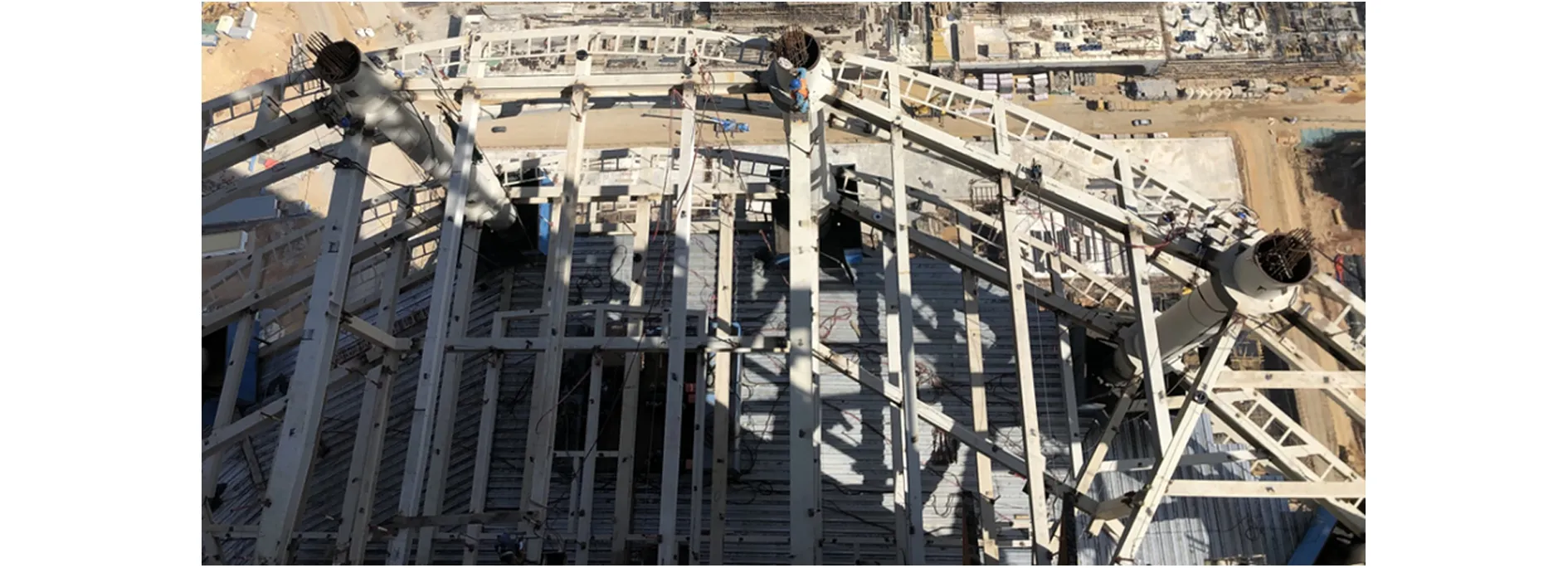
Fig.2 Steel structure installation of Iconic Tower
CFSTC is a kind of composite structural member, which is produced by pouring concrete into a steel tube. To enhance the connection between steel tube and concrete, shear studs are usually welded inside the steel tube. Utilizing the compressive and tensile properties of concrete and steel, CFSTC can compensate for each material’s defects. The steel tube limits the concrete and makes the concrete under 3D stress. This will intensify the strength and improve the plasticity, and toughness. It can effectively overcome the defect of high brittleness and poor ductility of concrete. On the other hand, the core concrete can postpone or avoid the buckling of thin-wall steel tubes, maximizing the strength of steel. CFSTC has outstanding advantages including its high bearing capacity, superior seismic performance, ease of construction, good fire resistance and other features. Compared with pure steel columns, CFSTC can save steel, and it can reduce the cross-section area and the self-weight of the structure when compared with reinforced concrete columns. In a word, CFSTC offers significant comprehensive advantages[2]. CFSTC conforms to the development trend of modern civil engineering toward large span, super high rise and heavy load, and also fulfill the requirements of construction engineering industrialization, providing both remarkable economic and social benefits as well as a wide range of future development opportunities.
The production of CFSTC can be divided into two steps. The first step is to install steel column. The steel structure can be installed quickly. For example, Iconic Tower takes an average of 4 days to complete each floor and the fastest installation only takes just 3 days. The second step is to cast concrete inside the steel column. When the steel structure is installed, the metal deck has not yet been paved, and the concrete slab has not been casted yet. These tasks normally take place 5 to 10 floors after the installation of the steel column, as shown in Fig.2. The casting of concrete in the steel column thus becomes a challenge by the lack of a safe platform where to pour concrete.
Concrete casting is a challenge in the production of CFSTC since the traditional method of pouring concrete from the top of a column has many drawbacks. Currently, the lift-up construction technique is the most advanced[2]. The CFSTC lift-up construction technique is vibration free, and high performance concrete is cast into the bottom of a steel column and raised to a predetermined height by pumping pressure. This new technique has been applied in high-rise buildings[3]. Compared with the traditional method, the lift-up construction technique has the following features:
1)Reduce the risk of work at height place and work intensity. All operations can be completed on a solid concrete slab, significantly improve the safety and convenience.
2)Reduce the construction period. The lift-up construction technique, which doesn’t require concrete to be poured from the top of column, won’t hinder the installation of the upper steel structure, which is on the critical path of the construction process. And all of the operations can be completed simultaneously with other construction activities.
3)Fast casting speed for concrete. When the pump line is connected to the steel column, concrete can be directly lifted up to a predetermined height by pressure without manual vibration, and concrete can be cast inside multiple floors of steel columns at once.
4)High quality concrete. To achieve good compactness and high quality concrete, the method uses high performance self-compacting concrete and adopts methods such as exhaust holes and casting speed control.
5)Streamline procedures for effective efficiency. The approach is more efficient requiring fewer operators, and follows straightforward procedures with less work and high efficiency.
Compared with traditional construction techniques, lift-up construction technique also has disadvantages, such as complex construction planning, high technique content, request for high performance concrete, the ease with which pump line can clog or burst, and other issues that necessitate the contractor’s possession of strong technical capability and construction management[4].
For the lift-up technique, it is necessary to make plans in advance. The plan includes determining the lift-up height of each casting operation, reserving casting holes during the shop drawing and production of steel columns, and reinforcing the casting holes during the production process. As shown in Fig.3, the circular plate cut from the column as repair welding plate was kept and attached with the column and transported to the site.

Fig.3 The reinforcement of casting hole and repair plate
The construction procedure of lift-up construction technique for CFSTC is described as follows:
1)In Fig.4, the conveying pipe is welded at the casting hole of the mounted steel column.
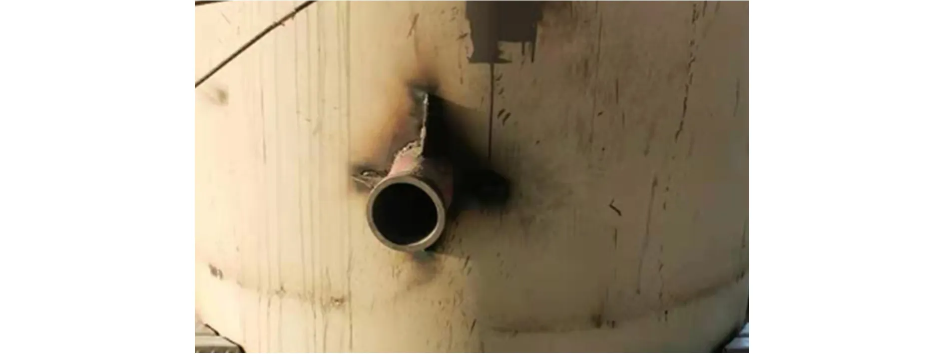
Fig.4 The conveying pipe at the casting hole
2)When the lift-up is completed, in Fig.5, install DN150 steel globe valve to prevent backflow of concrete.

Fig.5 The installation of globe valve
3)As shown in Fig.6, lubricate the pipe line with mortar before connecting it to the globe valve, and the mortar can not be cast into the steel column. When fresh concrete starts to flow out of the pipe and into the steel column, the pipe line must be connected with the globe valve to ensure the concrete can fulfill the column.
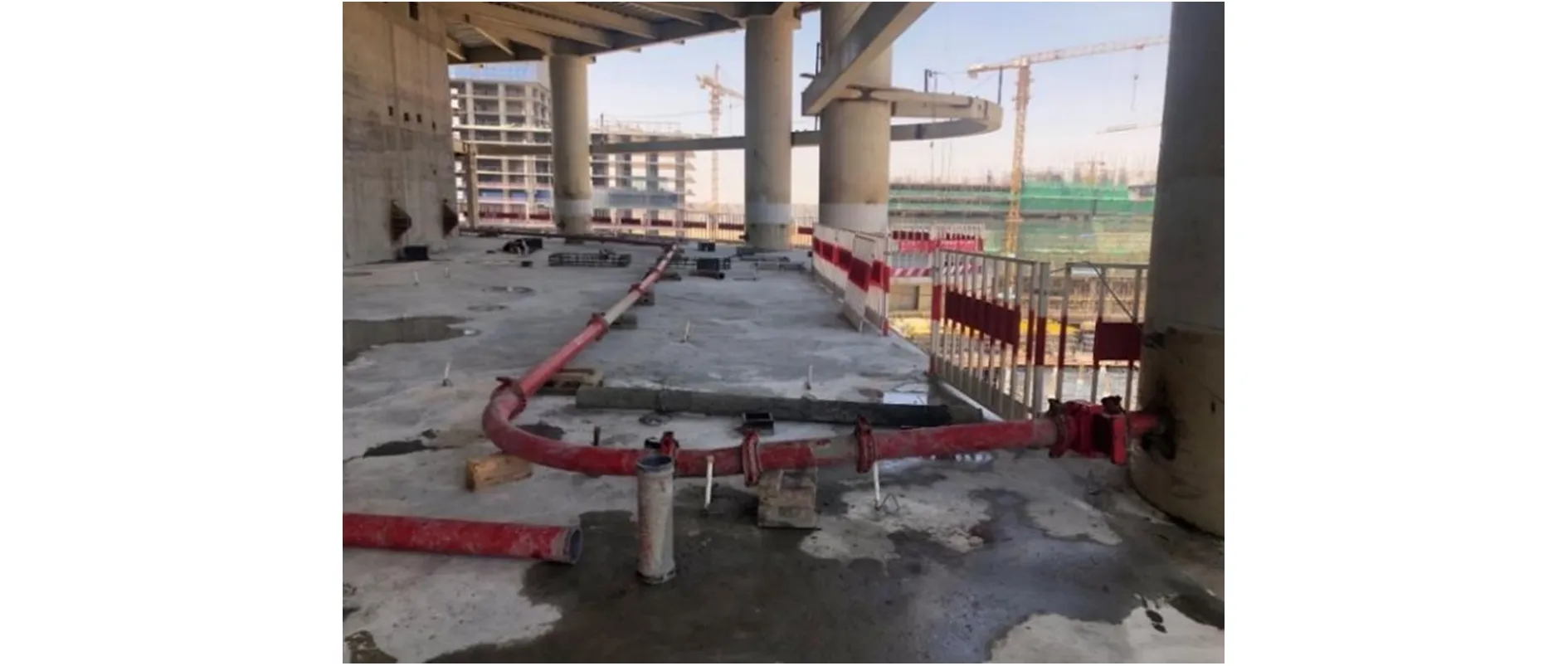
Fig.6 The installation of pipe line and lift-up of concrete
4)The steel column is continually cast with concrete, which is then lift up slowly by the pressure of the pump. When the concrete reaches the predetermined elevation, the pump pressure is stabilized for 2 to 3 minutes before closing the globe valve.
5)Disassemble the pump line, attach it to the subsequent pump and repeat the same operation.
6)When the concrete reaches 75% of the strength, the conveying pipe is turned off and clean the concrete. The casting hole can then be repaired using full penetration welding.Fig.7 shows the repaired casting hole following grinding.
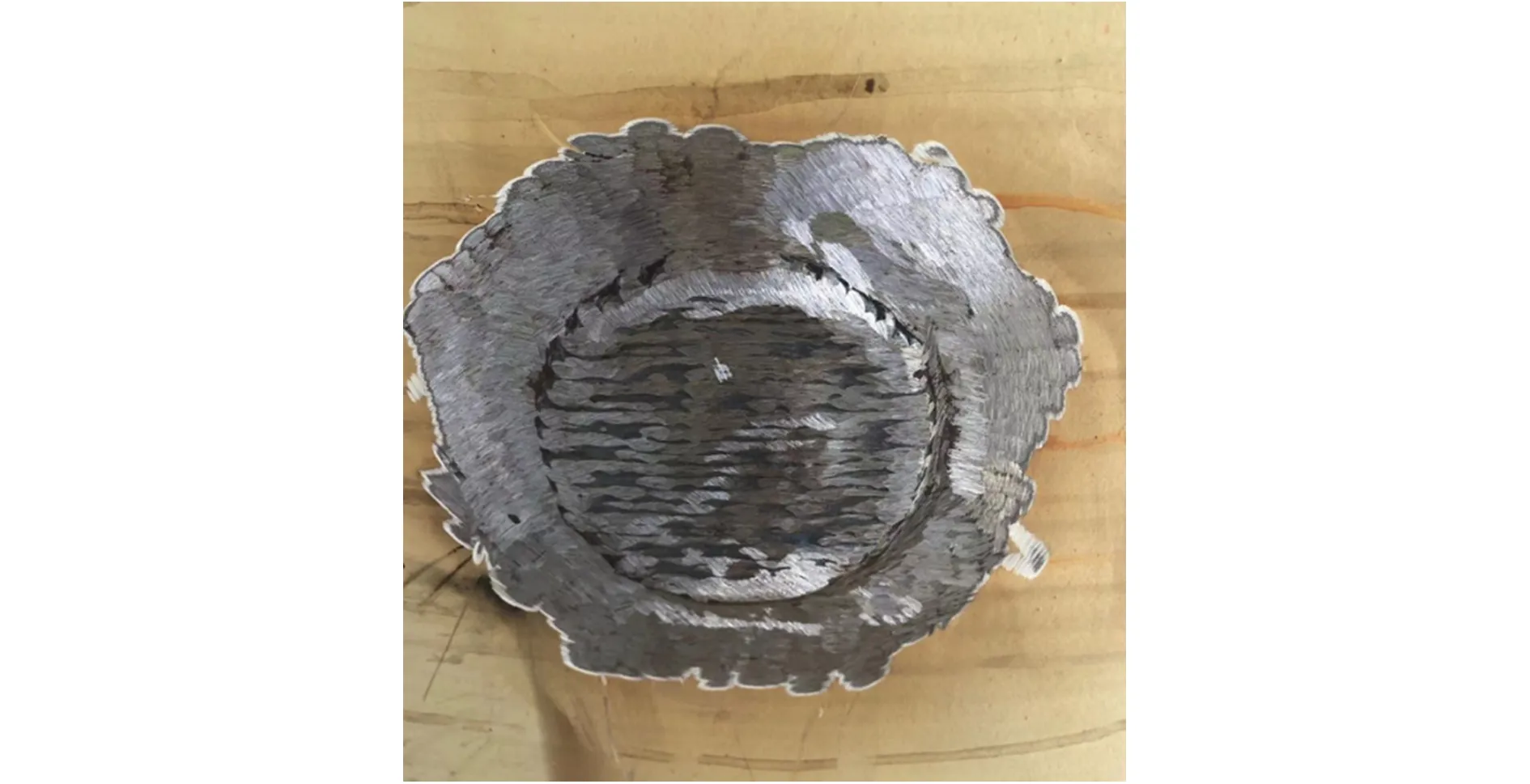
Fig.7 The repair of casting hole
The construction procedure of the lift-up construction technique of CFSTC is described as shown in Fig.8.

Fig.8 Construction procedure of lift-upconstruction technique
To ensure the quality of concrete cast inside steel columns, high performance self-compacting concrete is selected. The concrete must process high strength, high fluidity, low hydration heat, micro expansion, high stability and self-compacting qualities.
1)To ensure the high strength concrete, it is important to control the water-cement ratio by increasing the dosage of cement or cementitious materials and appropriately reducing the water quantity.
2)To guarantee high liquidity and low viscosity, the first step is to choose high quality cement and sand, cementitious materials, and limit the size of coarse aggregate to less than 20mm. The second step is to select high-quality admixture, which is the key to guarantee high liquidity and lowering viscosity.
3)Concrete’s natural tendency to shrink can cause a gap between the concrete interior and steel column. To avoid such gap, it is required to add an expansion agent to the mixture to prevent concrete from shrinking.
4)To fulfill the construction requirements, silica powder and ultra-fine slag must be added in the mixture to improve the stability of working performance and increase the compactness of concrete and reduce the heat of hydration.
The following performance requirements were met by the concrete for lift-up construction through the mixture design and simulation test: the expansion of fresh concrete must stay within a strict range within 750mm±50mm. The loss from 4h expansion must be less than 5%, and the loss from long-distance pumping expansion must be less than 10%.
The concrete pump’s output pressure is one of the distinguishing features, and the pressure loss along the pumping route are is related to the lift-up pressure. In the lift-up process, the required pumping pressurePmainly consists of three parts:
1)PressureP1is to overcome the frictional resistance of concrete flowing in the pipe line.
2)PressureP2is to overcome the resistance caused by concrete when passing through the pumping system accessories, elbow pipes and taper pipes.
3)PressureP3is to overcome the self-weight load of concrete in the vertical direction.
Generally, the pressure can be transformed into horizontal pipe distance and incorporated into the frictional resistance loss, since the pressureP2is relatively low in comparison with the overall pressureP.
Based on the analysis above, the pressure required for the concrete lift-up process of a steel column is determined as follows:
P=ξ(∑L+LE)+ρg(h1+h2)+Pl
(1)
Where:ξis the frictional resistance coefficient of the flowing concrete in the pipe (MPa/m);
∑Lis the pipe line’s total length from the concrete pump’s outlet (m);LEis the horizontal pipe length conversion factor for elbow pipes, taper pipes, etc. according to the resistance equivalence principle (m);h1is the height difference between the concrete pump and the casting hole of steel column (m);h2is the height at which concrete is cast inside the steel column (m);Plis the sum of the additional pressure loss caused by globe valves, the change cross section from a pipe to a steel tube, the exhaust hole in the steel columns, and so on (MPa).
The formulations above are explained as follows:
1)The frictional resistance coefficient ofξin the pump pipe can be determined by the formulation of Chinese code[5]or the measured data on the pipe line. The measured data are adopted in this project. As shown in Fig.9, two pressure measuring points are set on a horizontal pipe line, and the frictional resistance coefficientξis 0.017MPa/m, which can be obtained from the pressure difference.

Fig.9 Pressure measuring points on a horizontal pipe line
2)For each elbow pipe, the converting lengthlto set the horizontal length of elbow pipes and taper pipes is calculated asl=β/10 andβis the angle. For the taper pipe from 150mm to 125mm, each equal to 8m of horizontal pipes.
3)The pumping resistance in a steel pipe column is not taken into consideration. The concrete pouring into the steel column from the casting hole, according to the hydrodynamic formulation:
A1V1=A2V2
(2)
Where:A1is the inner area of pumping pipe (m2);V1is the velocity of the concrete flowing via the pumping pipe (m/s);A2is the inner area of a steel column (m2);V2is the velocity of concrete lifting up in a steel column (m/s). Normally, the diameter of a pumping pipe is 125mm or 150mm, and the diameter of a steel column is larger than 1 m. Because the area of a steel column is almost 100 times greater than a pumping pipe, the velocity of the concrete inside the steel column is only 1% of that inside the pumping pipe. The range of the velocity of concrete inside a steel column is typically 0.1cm/s to 0.5cm/s. It is assumed that the concrete flowing inside a steel column cannot create frictional resistance at that speed.
4)Pldetermines thatPl=0.5MPa can adequately compensate for the pressure loss by taking into consideration all of the pressure loss in the steel column, which is relatively small comparing withP.
Formulation 1 has a clear notion that is simple to calculate, and the datah1andh2are accessible on site and practical for application.
Lift-up construction technique utilizes pumping pressure to lift up concrete. While the pressure raises the concrete, it may also have negatively impact on the steel tube. The huge pressure may tear the steel tube and the structure safety can further be compromised[6]. Therefore, it is important to check the steel tube’s safety while under lifting pressure.
Since the steel tube’s diameter is significantly larger than the thickness, the column can be regarded as a thin-wall shell. The thin-wall pressure vessel correlation method can be applied for calculation, and the results can be used as an important reference. The study assumed that only tensile stress and shear force are subjected to the homogeneous element[7]. The stress is uniformly distributed along the thickness, and the influence of bending moment in the element is ignored[8]. The equilibrium equation of the element in shell are established as follows:
(3)

(4)
Where:tis the effective thickness of a steel tube (mm);ρ1andρ2are the radius of the longitude curvature and the latitude curvature (mm);σφandσθare the stress in the longitude and the latitude (MPa);pis the pressure on the inner surface of a steel tube (MPa); dφis the angle between two curvature radius of the element.
The concrete pressure exert on the steel column is axisymmetric, which is equal on the same section and perpendicular to the inner surface of the steel tube. Therefore,Pis constant at a certain elevation. The steel tube has the following formulations to explain the geometric relationship:
r=ρ2sinφ
(5)
dr=ρ1dφcosφ=dφ(ρ2sinφ)
(6)
Where:ris the circle radius (mm);for steel tubes with a radius ofr,ρ1=∞,ρ2=r. By substituting the geometric relations into the formulation above, we can derive bothσφandσθ.
Pressure capacity formulation of the steel tube is:
(7)
Where:Coefficient 1.2 is the safety factor, which takes the pulse of pumping pressure and other factors into consideration;Pfis the maximum vertical frictional resistance of lifting up the concrete in the steel tube (MPa),Pfcan be ignored because the velocity of the concrete in the steel column is low, as demonstrated in the last section;Gis the self-weight load of concrete in the steel tube at the determined height (MPa);diis the inner diameter of the steel column, (mm);[σ] is the design value of allowable stress of the material (MPa);φis the welding joint coefficient, for single-side welding,φis 0.9 when 100% of nondestructive test (NDT) and 0.8 for local NDT[9].
The formulation above can be used to verify the safety of the steel tube when applying the lift-up construction technique.
Advanced construction technique and management must be adopted to control and improve the concrete quality of CFSTC. The key construction technique and management steps in the process are listed as follows:
7.1 Setting venting holes
Each steel column has two venting holes installed on each floor. One locates 100mm above the floor and the other is 100mm below the beams. The venting hole is 20mm in diameter. Venting holes allow air to be released from the columns during the casting process, improving the compactness of concrete. Additionally, the venting holes serve as observation holes to identify the state of the concrete by viewing the slurry overflow throughout the casting process. If the slurry outflow is uniform, the fluidity and workability of the concrete in the column can perform well.
7.2 Casting speed control
Controlling the concrete’s lifting up speed in the steel columns is important. The compactness of the concrete suffers if concrete casts too fast. When concrete casts too slowly, it indicates that the casting process takes a lengthy time. This causes a decline in concrete performance, pump blockage, poor compactness, and other problems.
7.3 Casting height control
The optimal casting height can be calculated based on the concrete amount, casting time, concrete performance and settlement. Normally, 3 to 6 floors of concrete can be poured into steel columns each time, with a maximum casting height of 30 meters.
There are two methods to ascertain the casting height. One is to calculate concrete quantity to be pumped. Check the concrete quantity in the pump pipe and in the steel column to measure the amount of concrete that need to be pumped. Then, close the globe valve when the predetermined concrete amount is reached. The other method is to monitor the casting height of concrete through the observation hole, and close the globe valve when the predetermined height is reached.
1)Plastic hammer knocking
During the casting process, the steel column is struck by plastic hammers to eliminate the small bubbles and to test the compactness of the concrete.
2)Compactness detection
To identify the degree of the defect at a suspicious position for further detection, the compactness of concrete will be checked by percussion method and ultrasonic nondestructive testing. If the concrete is not completely dense, the repairing method is to drill holes in the column and grout. The state of the concrete in the casting hole can serve as an indicator to the compactness of concrete to some extent. After removing the conveying pipe, the concrete in the casting hole of the steel column is uniform and compact, as shown in Fig.10.
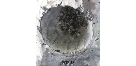
Fig.10 The state of concrete at a casting hole
3)Curing of concrete
By watering the concrete through the upper casting hole and keeping the water at least 50mm deep on the concrete surface during the curing process, the concrete can be cured within 8~12 hours after being lifted up into the steel column.
The lift-up construction technique for concrete-filled steel tubular column is a vibration free construction method. A high performance self-compacting concrete is poured into the casting hole of a steel column, then raises the concrete-filled steel column to a predetermined height by pumping pressure. Based on the analysis of the technical characteristics, construction procedure, high performance self-compacting concrete, lift-up pressure calculation, explosion-proof calculation, and quality control points of the lift-up construction technique, the following findings can serve as a guide for similar projects.
1)The lift-up construction technique for composite columns is an advanced concrete casting technique, and has been applied in the construction of high-rise buildings. It has the advantages of reducing the risk of work at height and work intensity, shortening the construction period, and high efficiency.
2)The lift-up construction techique needs to plan in advance, and the casting hole must be reserved during the shop designing and production of steel columns.
3)High performance concrete is selected for the lift-up construction technique. High performance comprises features includes high strength, high fluidity, low hydration heat, micro expansion, high stability and self-compacting, and so on.
4)The pumping pressure required for the lift-up process mainly consists of three parts: ①The pressure needed to overcome the frictional resistance of the concrete flowing in the pipe line; ②The pressure needed to overcome the resistance caused by concrete when passing through the pumping system accessories, elbow pipes and taper pipes; ③The pressure must overcome the self-weight load of concrete in the vertical direction.
5)The lift-up pumping pressure may have negative impact on steel columns, so it is necessary to check the safety of steel column under pumping pressure.
6)During the casting process of lift-up construction technique, it is important to follow the steps including setting venting holes, casting speed control, casting height control, compactness detection and concrete curing to improve the concrete quality.
猜你喜欢 工程局开罗分公司 水利第二工程局河南水利年鉴(2020年0期)2020-06-09水利第一工程局河南水利年鉴(2020年0期)2020-06-09水利第二工程局河南水利年鉴(2017年0期)2017-05-19水利第一工程局河南水利年鉴(2017年0期)2017-05-19General Electric’s Innovation科学与财富(2016年34期)2017-03-23COACH Inc. in 2012Its Strategy in the “Accessible”Luxury Goods Market科学与财富(2016年34期)2017-03-23IWI美国分公司ACE GAR1651步枪轻兵器(2017年2期)2017-03-10开罗一教堂遭炸弹袭击环球时报(2016-12-12)2016-12-12分公司红领巾·成长(2015年8期)2015-09-10开罗伊斯兰教老城读者(乡土人文版)(2014年2期)2014-01-11 相关热词搜索:混凝土,钢管,施工技术,