Adaptive,Tracking,Control,for,Diffractive,Film,Based,on,Nonlinear,Sliding,Mode
时间:2023-03-04 14:35:05 来源:千叶帆 本文已影响人
,*,,,
1. College of Aerospace and Civil Engineering, Harbin Engineering University, Harbin 150001, P.R. China;
2. Marine Design and Research Institute of China, Shanghai 210110, P.R. China
Abstract: A nonlinear sliding mode adaptive controller for a thin-film diffractive imaging system is designed to achieve accurate pointing direction over the attitude of subarrays in large-diameter mirror arrays. The kinematics and dynamics equations based on error quaternion and angular velocity are derived, and a diffractive thin-film sub-mirror array controller is designed to point precisely. Moreover, the global stability of the controller is proved by the Lyapunov method. Since the controller can adaptively identify the inertia matrix of each sub-mirror system, it is robust to bounded disturbances and changes in inertia parameters. At the same time, the continuous arctangent function is introduced, which is effectively anti-chattering. The simulation results show that the designed controller can ensure the accurate tracking of the diffractive film in each sub-mirror in the presence of rotational inertia matrix uncertainty and various disturbances.
Key words:attitude tracking;
sliding mode control;
diffraction imaging;
optical imaging system;
Lyapunov function
The increasing focus length and payload lens diameter caused by the demands of ever-increasing Earth observation resolution have exceeded the launching ability of rockets[1]. As a new type of imaging technology, the diffractive thin-film imaging technology has the advantages of lighter weight, variable surface shape, easier to be folded and unfolded, lower surface density, and lower cost compared with traditional optical imaging payloads[2-3]. The diffractive thin film is one of the most promising practical approaches for imaging systems to solve the problem of ultra-large aperture and ultralight load imaging systems in space.
In 1998, the Eyeglass project, whose telescope system consists of an objective lens satellite and an eyepiece satellite, was proposed by the Lawrence Livermore National Laboratory (LLNL) in the United States. And the feasibility of diffraction imaging technology was proved by the ground prototype[4-5]. In 2010, the membrane optical imager realtime exploitation (MORIE) satellite research program, which is greatly improved based on the “Eyeglass Program”, was announced by the Defense Advanced Research Projects Agency (DARPA)[6-7].
The diffraction imaging system consists of an imaging satellite and a diffraction film satellite. The diffractive film satellite is equipped with a film primary mirror which is covered with small nanoscale etched holes for imaging based on the diffraction principle. The rest of the imaging system is built on the imaging satellite. On the one hand, due to different orbital altitudes of binary satellites, the diffractive film sub-mirrors need to adjust its pointing in real-time to ensure the quality of images. On the other hand, the diffraction imaging system is in a complex space environment, where disturbing factors such as solar light pressure, non-spherical perturbation of the Earth, and atmospheric drag also have impact on the pointing accuracy. Therefore, high accuracy tracking and pointing control of diffraction films is essential.
The control of the separate diffractive imaging system is the key to ensuring the relative attitude pointing, so it has gained extensive interest in recent years. The representative one is a set of orbital parameters of the co-located diffraction imaging system designed by Sun et al.[8], which also showed the feasibility of post-disaster remote sensing. The designed co-located diffractive satellite system can simultaneously provide an essential reference for post-disaster emergency response. Presently, the relative control of diffraction imaging satellites mainly draws on the relative attitude control of the binary satellite formation. Considering the uncertainty of angular velocity, the impulse variance control method for the binary satellite based on the observer-based was proposed, which solved the stability problems with parameter uncertainty, pole constraint, variance constraint, and limited thrust[9-10]. An adaptive sliding mode control scheme is designed to solve the high-precision tracking control of the formation spacecraft[11-12]. Combined with the characteristics of the integral sliding mode segment, an adaptive integral sliding mode control law was proposed, which solved the problem of excessive adaptation of switching gain in the attitude tracking control of spacecraft[13]. Sun et al.[14]designed a robust adaptive feedback-limited controller, where the modified Rodrigues parameters were used to describe the attitude tracking dynamics model. Xu et al.[15]used the square root volumetric Kalman filter to estimate the relative position and calculate the desired attitude. Correspondingly the error attitude dynamics equation was described based on the modified Rodrigues parameter, and the backstepping adaptive control law was used to control the pointing and tracking of the spacecraft. Yin[16]proposed a multi-loop recursive tracking attitude control strategy, and the integral term of attitude tracking error was introduced into the attitude tracking dynamic system so that the structure of the attitude tracking system was changed.
For diffraction imaging control of the diffractive film, there are few archives introducing conception and design. Hence, we take the satellite attitude control method as a reference to implement film-pointing control. In order to improve the convergence rate and system life, a variable structure sliding mode control method for satellite attitude maneuver was proposed, where the constraint relationship between the control parameters and the system performance was given to prevent the system state from exceeding its upper bound[17]. A method of finite time adaptive integral sliding mode controller was proposed to guarantee the spacecraft attitude tracking target attitude[18]. In the presence of uncertain parameters and unknown inputs, a robust control method was proposed for rigid spacecraft attitude stabilization using the state-dependent indirect Chebyshev pseudospectral method[19], and the design of a passivity-based adaptive robust control for attitude tracking of a three-axis satellite was investigated[20]. Although these methods can well solve the relative attitude control problem of the double-satellite formation, the controller of thinfilm mirror array satellites with limited motion of thin-film mirrors for diffraction imaging has not been studied.
In this paper, we will analyze the desired pointing angle for high-precision attitude tracking control of the diffractive film sub-mirror, build an attitude tracking error model, and following this, the diffractive thin-film sub-mirror array control schemes will be designed. This paper is organized as follows. Section 1 states the model establishment of the diffraction imaging system. The primary research is developed in Section 2, in which the adaptive controller of a diffractive thin-film sub-mirror array is proposed to achieve highly accurate tracking in finite time. And the stability of the proposed controller is proven using the Lyapunov stable theory. Then, the numerical results are simulated and the PD controller is introduced for comparison tests with the controller proposed in Section 3. Finally, conclusions are given in Section 4.
1.1 Diffraction imaging system description
The diffraction imaging system consists of the thin-film diffraction mirror array satellite and imaging satellite, which maintains a formation configuration to realize the high-precision imaging function of a heterogeneous binary satellite. The imaging satellite is treated as a particle to simplify the model. Each diffractive thin-film sub-mirror rotates around its pitch axis so that the plane of each thin-film submirror is perpendicular to the optical imaging path, thereby realizing real-time tracking and orientation of the imaging satellite. The imaging position relationship is shown in Fig.1.

Fig.1 Binary satellite thin film diffraction imaging system
1.2 Diffraction mirror array satellite model
In this paper, the research object is the thinfilm diffractive mirror array satellite for diffraction imaging of nano-scale etched pinholes. It is mainly composed of three parts:
Central body structure, diffractive film sub-mirror array, and truss. The diffractive film sub-mirror, which is unfolded and flattened by the truss, can be twisted and adjusted independently[21-22]. The sub-mirrors orient to the imaging satellite by rotating around their pitch axis. As shown in Fig.1, the earth-centered inertial (ECI) frameO-XYZis a coordinate system, in which the origin is the center of mass of the Earth, theXYplane is the Earth’s equatorial plane at the moment of J2000, and theX-axis points to the equinox at the moment of J2000. The spatial configuration of the thin-film diffraction mirror array satellite and diffractive film sub-mirror system are shown in Fig.2. The thin-film diffractive mirror array satellite consists of 24 diffractive thin-film sub-mirrors in the inner and outer circles. To facilitate controller design, the outermost mirror pointed by theX-axis of the thin-film diffractive mirror array satellite body coordinate system is numbered asα1, and other mirrors are numbered counterclockwise, as shown in Fig.2.romi(i=1,2,…,n) is the distance vector of the sub-mirror from its centroid in the thin-film diffraction satellite body coordinate system, where the subscript miisith diffractive thin-film sub-mirror andnis the total number of mirrors in the thin-film diffraction mirror array satellite.

Fig.2 Thin-film diffraction mirror array satellite sub-array system
1.3 Desired attitude angle model of diffractive film
The desired attitude of the diffractive film should be perpendicular to the optical path of the imaging satellite. In the process of high-precision imaging, the model is simplified for specific problems under certain assumptions to derive the desired attitude angle. The basic assumptions are given as follows.
(1) In the process of maintaining the formation configuration, the imaging satellites and the thinfilm diffraction mirror array satellites are oriented to the ground, whose body coordinate system coincides with the orbital system.
(2) The imaging satellite can be regarded as a particle whose center of mass coincides with the geometric center.
(3) The centroid displacement of the thin-film diffractive mirror array satellite caused by the rotation of the diffractive thin-film sub-mirror is a negligibly small amount.
The desired attitude information of each diffractive thin-film sub-mirror system is related to the relative distance vector of the thin-film diffractive mirror array satellite and the imaging satellite.
The relative distance vector of the binary satellite in the ECI frameO-XYZcan be expressed as

wherer1andr2represent the vectors from the imaging satellite and the thin film diffraction mirror array satellite to the center of the earth in the ECI frameO-XYZ, respectively.
The distance vectorrsifrom the imaging satellite to the centroid of the diffractive film sub-mirror can be expressed as

whereLeois the coordinate transformation from the orbit reference frame to the ECI frame[23]. It can be written as

where c and s denote cos(·) and sin(·), respectively;
Ωis the right ascension of the ascending node of the orbit,ithe inclination of the orbit,u=f+ωa latitude parameter representing the position of the spacecraft relative to the ascending node,fthe true anomaly, andωthe argument of perigee. The expected pointing angle of each diffractive thin-film sub-mirrorαiin the high-precision imaging configuration maintaining mode is shown in Fig.3, which can be expressed as

Fig.3 Desired pointing angle of diffractive film sub-mirror system

1.4 Attitude tracking error model of diffractive film
The relative attitude error kinematics and dynamics models of diffractive thin-film sub-mirrors represented by quaternions can be established as[24]

wherei=1,2,…,nrepresents theith diffractive thin-film sub-mirror,Ji∈R3×3the moment of inertia matrix, andωtidesired attitude angular velocity;
ωei=ωbi-Ciωtidenotes the angular velocity error between the actual attitude and the desired attitude, whereωbirepresents the attitude angular velocity, and the specific expression of the attitude transformation matrixCiiswith ‖Ci‖=1,CiTCi=1,C˙i=-ω×eiCi, (·)×denotes a 3×3 skew-symmetric matrix,qei=[qei1,qei2,qei3]Tis the vector part of the quaternion for the attitude error.TiandTdiare the control moment and bounded disturbance, respectively.I3is the identity matrix. The attitude tracking errorQei=[qei0,qTei]Tdenotes the relative attitude error from the actual attitude to the desired attitude, which can be obtained as whereQbiandQtirepresent the actual and desired attitude quaternion, respectively. ⊗ represents the quaternion multiplication.

In this section, we propose a novel nonlinear synovial surface with the inverse tangent signum function. Then, we design the adaptive attitude tracking control schemes for the thin-film diffraction sub-array mirror system in the presence of inertia uncertainties and external disturbances[25]. The algorithm is based on a nonlinear sliding mode and has the advantages of finite time tracking, fast, accurate, anti-chattering, suppressing inertial uncertainty, and adaptively identifying the upper bound of interference. The traditional symbolic sliding mode variable structure control system suffers from severe jitter and vibration. The introduction of an arctangent function eliminates the jitter caused by the sign function and ensures fast global convergence of the system state on the sliding mode plane.
For each sub-mirror in the thin-film diffractive mirror array satellite, the nonlinear synovial surface can be defined as

whereKis the positive definite diagonal matrix, and arctanqei=[arctanqei1arctanqei2arctanqei3]T. The attitude error quaternion has the property ofq2ei0+·qei=1, we have ∀t≥0,|qeij|≤1,j=1,2,3.

For ∀ξ∈R and ∀a∈R, the arctangent function arctanξyields

Assuming that the moment of inertiaJiof the diffractive film sub-mirrorαiis an unknown positive definite symmetric constant matrix[26]. The disturbance torqueTdiis bounded. The estimated error of the inertia parameter can be defined as

whereji=[Ji11Ji22Ji33Ji12Ji13Ji23]Trepresents the inertia parameter of the diffractive film submirror numberedαi, whose estimated inertia parameter is
It is known from the assumption that the inertia parameter of the diffractive film sub-mirror is an unknown constant, then there isjˉi=-j~i.
The linear operator is defined as

For ∀ξ=[ξ1ξ2ξ3]T∈R3, there isJξ=L(ξ)j.
Multiplying the derivative of Eq.(8) to the left byJiand substituting Eqs.(5) and (6) into it obtains

Applying the linear operatorL:R3→R3×6,Eq.(15) is simplified as

where

Considering the attitude tracking system described with an unknown inertia matrix and disturbance moment, if Eq.(18) is satisfied, the robust adaptive control law expressed in Eq.(19) and the parameter adaptive adjustment law expressed in Eq.(20) can ensure thatandare uniformly ultimately bounded(UUB). That isand, the error angular velocityωeiand the error quaternionqeiof each diffractive thinfilm sub-mirror asymptotically converge into zero[27].

whereε,σandτare undetermined constants;
k=diag(k1,k2,k3),kl>0(l=1,2,3);
is an estimate ofTdXi;
is estimation error, which is defined as(0) is the estimated initial value ofrepresents the positive definite diagonal matrix.
Proof
The following Lyapunov candidate function is selected as


Inserting Eqs.(10, 19) into Eq.(22) yields

The diffractive thin-film sub-mirror is selected to verify the effectiveness of the proposed method, as shown in Fig.4. The distances from the centroid of the diffractive film outer mirrorOouterand the inner circle mirrorOinnerto the centroid of the diffractive film satelliteOdfare set as 10 m and 5 m, respectively.
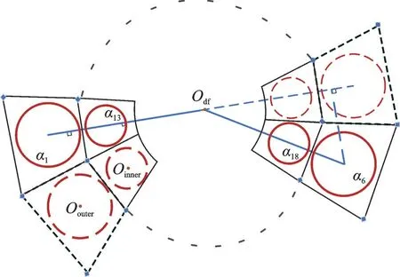
Fig.4 Diffractive film sub-mirror layout position
3.1 Performances of the proposed control method
The position of the imaging satellite is 100 meters in the direction of the film diffraction satellite vector. The orbit of the binary satellite is shown in Table 1.

Table 1 Detailed properties and characteristics of the binary satellite thin-film diffraction imaging system
Four sub-mirrors are selected for numerical simulations, and their position parameters are shown in Table 2. The nominal inertia matrix of the diffractive film sub-mirrorαiis

Table 2 Position parameters of the selected diffractive film sub-mirror αi

The initial conditions of quaternion and angular velocity of each sub-mirror of the diffractive film satellite are:Qbi(0)=[1 0 0 0]Tandωbi(0)=0 rads. The desired states of the tracking error quaternion and angular velocity are selected asQei=[1 0 0 0]Tandωei(t)=0 rads, respectively. In addition, the required maneuver angle is calculated by Eq.(4).
The external disturbance of the diffractive film sub-mirrorαiis considered as


The control torque is limited to [-0.2,0.2]N·m.
The performances of the thin-film diffraction sub-array mirror controller are depicted in Figs.(5—10), respectively, where the numbersi(i=1,6,13,18) are selected for presentation. As can be seen from Figs.5 and 6, the diffractive film sub-mirror settles in approximately 200 s, and the tracking error quaternion and attitude angle approach the desired value in a well-behaved manner in a finite time. After 200 s, the upper bound of attitude angle error is 0.001° even though external disturbances induced by inertia uncertainties and variations affect the sub-mirror system. These two figures show that the controller can steer the diffractive film to the attitudes that point to desired imaging target and imaging satellite in a finite time.
Attitude angular velocity error and control torque ofαiare depicted in Figs.7 and 8, respectively. Fig.7 shows that the attitude angular velocity error ofαican reach the desired value in finite time. The chattering can be avoided effectively, as shown in Fig.8.

Fig.5 Error quaternion variation curve

Fig.6 Attitude angle error change curves

Fig.7 Attitude angular velocity error change curves

Fig.8 Control torque curves
The nonlinear sliding mode adaptive controller of the diffractive film sub-mirror array can realize high-precision tracking and stable orientation of the posture of each sub-mirror.
Fig.9 shows the comparison of actual attitude angle ofαiand the desired attitude pointing angle, whereαipitchbandαipitchtare actual and desiredyaxis attitude angles ofαi, respectively.

Fig.9 Comparison of actual and expected attitude angles of αi
By comparison, it is more significant to show that within 150 s, the pitch angle converges to the desired tracking pointing angle.
Fig.10 shows that the adaptive estimated values of the disturbance torque converge into constant values over time. The uncertainty of the disturbance torque of each sub-mirror system is considered so that the control system can adapt to the parameters of satellite inertia and has strong robustness.

Fig.10 Disturbance torque estimates for αi
3.2 Comparison with the PD control method
To show the performance advantages of the controller proposed in a better comparison, a PD controller such as

is introduced, where the parameters are chosen as=0.1 ,=5, and the control torque limit is [-0.2,0.2]N·m. One of the diffractive thin-film sub-mirrors,α1, has been chosen as representative. For comparison, the simulation results for both controllers are shown in Fig.11. The subscript pb represents the PD controller, the subscript t the nonlinear sliding mode controller and the subscript b the expected value.

Fig.11 Controller performance comparison
The diffraction film rotates around its pitch axis (Y-axis) to complete the orientation of the imaging satellite. Therefore, the pointing angle maximum steady-state error in theY-axis and the 2-Norm of the error in the three-axis attitude angle (RMS) of the diffracted film are taken as evaluation indicators.
The results are shown in Table 3. As can be seen from Table 3, the nonlinear sliding mode controller can achieve significant improvements in accuracy and convergence time compared to the PD controller.

Table 3 Performance comparison of two controllers
It can be concluded from numerical results that the designed sliding mode controller with the continuous arctangent function can effectively suppress the chattering of the system and ensures the smooth convergence of the attitude angle. The control system can meet the accuracy requirements of the precise configuration for the heterogeneous binary satellite diffraction imaging system and has a fast response speed.
A nonlinear sliding mode adaptive controller is designed for the control problem of thin-film diffractive sub-mirrors with high-precision attitude tracking and pointing requirements in the binary satellite thin-film diffraction imaging system. In addition, the global stability of the controller is proved mathematically. The designed controller can adapt to the parameters of satellite inertia and has strong robustness to disturbance torque. Finally, through numerical simulation and comparative verification, the following conclusions are drawn.
(1) The controller can meet the requirements of attitude control accuracy and stability in a heterogeneous binary satellite diffraction imaging system, which is posture tracking and orientation of imaging eyepieces by diffractive film sub-mirrors.
(2) The controller has strong robustness, which can adapt to the uncertainty of the rotational inertia and disturbance torque of each sub-mirror.
(3) The controller introduces a continuous arctangent function, which effectively eliminates the chattering of the system and further ensures the control accuracy of the pointing angle of the diffractive film sub-mirror.
相关热词搜索:Control,Diffractive,Adaptive,